

How Single-Screw Pumps Help in High-Pressure Liquid Handling
Single-screw pumps, also known as progressing cavity pumps, have become a key technology for industries that need reliable high-pressure liquid handling. From viscous crude oil and slurries to shear?sensitive food products and aggressive chemicals, single-screw pumps deliver stable flow, high discharge pressures, and excellent suction performance.
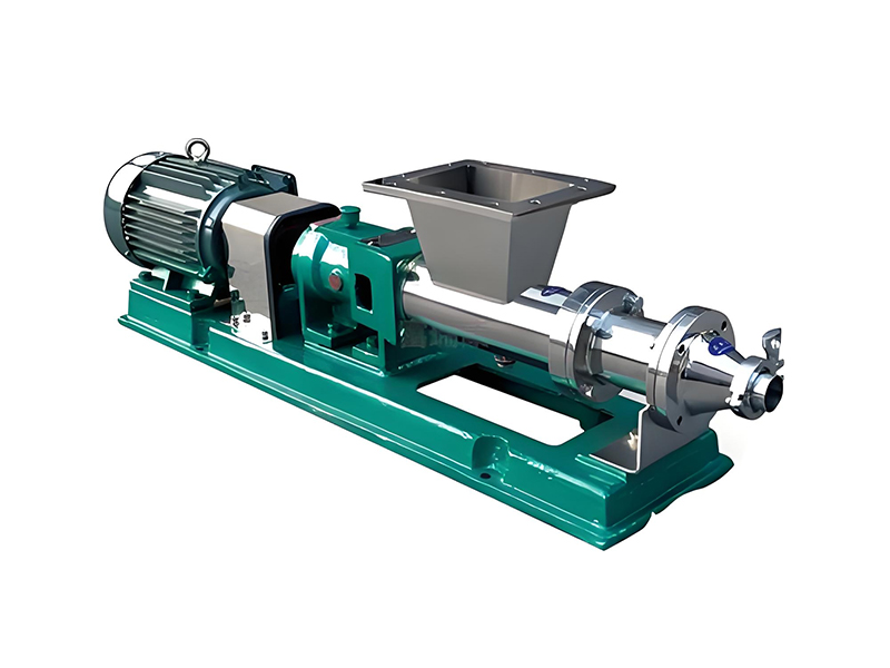
A single-screw pump is a positive displacement pump that transfers liquid by means of a single rotating screw (rotor) inside a fixed helical cavity (stator). The geometry of the rotor and stator creates enclosed cavities that move the fluid axially from suction to discharge as the rotor turns.
Because each cavity is sealed from the next, the pump delivers a nearly pulsation-free flow that is proportional to speed. This makes the single-screw pump particularly effective in high-pressure liquid handling where accuracy, stability, and protection of the product are essential.
Key characteristics that make single-screw pumps suitable for high-pressure applications include:
High differential pressure in a compact footprint (often up to several tens of bar, depending on design)
Ability to handle very high-viscosity and non-Newtonian fluids
Low shear and gentle conveying for sensitive liquids
Excellent self-priming and suction lift capability
Continuous, non-pulsating volumetric flow
A single-screw pump (progressing cavity pump) is a type of rotary positive displacement pump that consists of a metallic, single-start helical rotor and an elastomeric or metallic stator with a double-start helix. As the rotor turns within the stator, cavities form and progress from the suction side to the discharge side.
Rotor – A single metal screw with a precise helical profile.
Stator – A stationary sleeve with an internal double-helix cavity, usually made of elastomer or metal.
Drive shaft / coupling rod – Connects rotor to drive, compensates for eccentric motion.
Suction casing – Admits liquid into the pump cavities.
Discharge casing – Directs pressurized liquid to the piping system.
Sealing arrangement – Mechanical seal, packed gland, or cartridge seal to prevent leakage.
Bearings and drive – Support and rotate the rotor at controlled speed.
The working principle of a single-screw pump can be summarized as follows:
As the rotor turns inside the stator, a series of closed cavities is formed at the suction end.
These cavities are sealed by the interference fit between rotor and stator.
The rotation causes cavities to move from suction to discharge, carrying trapped liquid forward.
The volume of each cavity remains nearly constant; the flow rate therefore depends mainly on the pump speed and geometry.
Because the cavities are always filled and there is minimal slip, the pump is capable of generating high discharge pressure.
This progressing cavity action is the reason single-screw pumps are often simply called PC pumps or Progressive cavity pumps.
In many process industries, operators need to move liquids at relatively high differential pressures while ensuring stable flow and avoiding damage to the product. Single-screw pumps are widely used in high-pressure liquid handling because they can achieve pressure increases in stages along the pump length.
The pressure capability of a single-screw pump is directly related to:
The number of cavities (stages) in the rotor–stator assembly
The tightness of the rotor–stator fit
The mechanical strength of rotor, stator, and housing
Each stage (cavity pair) contributes a certain pressure increase. By adding more stages, the pump can handle higher discharge pressures. For example, a multistage single-screw pump may be designed to handle pressures in the range of 24–48 bar or even higher, depending on design and materials.
For high-pressure liquid handling, single-screw pumps provide multiple benefits:
Stable flow at high pressure – Minimal pulsation keeps downstream instruments and piping under steady conditions.
High efficiency in viscous service – Single-screw pumps maintain capacity even when viscosity increases dramatically.
Low NPSH requirement – Good suction performance reduces risk of cavitation in high-pressure systems.
Bidirectional operation – Many designs can run in either direction, simplifying process design.
Handling of solids – Slurries and liquids with entrained solids can be pumped at high pressure with proper design.
When choosing a pump for high-pressure applications, it is helpful to compare single-screw pumps with centrifugal pumps, gear pumps, and other positive displacement pumps.
| Pump Type |
|---|
| Typical Pressure Range |
|---|
| Best For Viscosity Range |
|---|
| Flow Pulsation |
|---|
| Shear Impact |
|---|
| Solids Handling |
|---|
| Single-Screw Pump (Progressing Cavity) |
| Up to ~48 bar or more (design dependent) |
| Low to extremely high viscosity (water-like to pastes) |
| Very low pulsation, nearly continuous |
| Low shear, gentle pumping |
| Good, handles slurries and soft solids |
| Centrifugal Pump |
| Typically up to ~16 bar per stage (higher with multistage) |
| Low to medium viscosity |
| Moderate pulsation (depends on design) |
| High shear in some designs |
| Limited, not ideal for large solids or high solids content |
| Gear Pump |
| Medium to high pressure |
| Low to medium-high viscosity, clean liquids |
| Moderate pulsation |
| Moderate to high shear |
| Poor, requires clean fluids |
| Piston / Plunger Pump |
| Very high pressure (hundreds of bar) |
| Low to medium viscosity, relatively clean |
| High pulsation, requires dampening |
| Moderate shear |
| Limited solids handling |
| Diaphragm Pump |
| Medium to high pressure |
| Low to medium viscosity |
| Noticeable pulsation |
| Low shear |
| Can handle some solids depending on design |
Single-screw pumps offer a unique combination of high pressure capability, low shear, excellent solids handling, and wide viscosity range. This combination is difficult to match with other pump types, especially when a continuous, non-pulsating flow is required.
The advantages of single-screw pumps become particularly clear when processes demand stable, repeatable performance at elevated pressures.
Because the displacement per revolution is almost constant, flow is directly proportional to pump speed. This volumetric performance is important in:
Metering and dosing at high pressure
Feeding filters, membranes, and separators
High-pressure injection of additives and chemicals
Unlike centrifugal pumps whose performance drops steeply with increasing viscosity, single-screw pumps maintain flow even as viscosity rises. Applications include:
Crude oil, bitumen, and heavy fuel oils
Food pastes, dough, and syrups
Paints, resins, polymers, and slurries
The smooth, progressing cavities gently move product from suction to discharge without abrupt velocity changes. This is important when pumping:
Shear-sensitive emulsions and suspensions
Biological products and cultures
Food products with particulates
Single-screw pumps are self-priming and can achieve significant suction lifts when properly installed. In high-pressure systems, this improves reliability by reducing cavitation risk at the pump inlet.
With appropriate material selection, single-screw pumps can convey slurries, grit, and soft solids at elevated pressures. The slow rotational speed and robust stator design help reduce wear compared to many alternative pump types.
Several design and construction features of single-screw pumps directly influence their suitability for high-pressure liquid handling.
The number of stages, pitch, and profile of the rotor and stator define pressure capability and efficiency:
Single-stage designs for low to medium pressures with higher flow rates.
Multistage designs for higher pressure at modest flow.
Optimized pitch to balance slip, efficiency, and mechanical stress.
Materials must withstand both mechanical loading and fluid chemistry under high pressure.
| Component |
|---|
| Typical Materials |
|---|
| Selection Criteria |
|---|
| Rotor |
| Stainless steels, tool steels, duplex steels |
| Strength, corrosion resistance, wear resistance |
| Stator (Elastomer) |
| NBR, EPDM, FKM, HNBR, specialty elastomers |
| Chemical compatibility, temperature resistance, elasticity |
| Stator (Metal) |
| Stainless steel, special alloys |
| High-temperature service, aggressive media, high pressure |
| Housing / Casing |
| Carbon steel, stainless steel, cast iron |
| Design pressure, corrosion resistance, cost |
| Seals |
| Ceramic, silicon carbide, carbon, elastomers |
| Pressure rating, shaft speed, fluid compatibility |
High-pressure single-screw pumps rely on robust sealing systems to prevent leakage and ensure safety:
Single mechanical seals for moderate pressures and benign fluids.
Double mechanical seals with barrier fluid for hazardous or high-pressure fluids.
Packing glands in certain low-cost or less demanding services.
High-pressure operation imposes axial and radial loads on the pump shaft and rotor. Heavy-duty bearings and reinforced drive shafts are used to:
Maintain precise rotor–stator alignment
Minimize deflection under high pressure
Extend service life in continuous operation
Single-screw pumps are applied across multiple industries for high-pressure transfer, dosing, and feeding duties.
Crude oil transfer over long distances at elevated pressure
Multiphase fluid handling with gas, oil, and water mixtures
Injection of chemicals, inhibitors, and additives into pipelines
Transfer of polymers, resins, adhesives, and viscous intermediates
Metering of catalysts and high-value chemicals under pressure
Feeding reactors, filters, and high-pressure vessels
Pumping fruit concentrates, syrups, sauces, and dairy products
Transfer of dough, mashed foods, and soft-solid mixtures
Feeding high-pressure homogenizers or pasteurizers
Dosing of polymers and flocculants at controlled high pressure
Pumping sludge and thickened biosolids
Feeding filter presses and membrane systems
Transfer of ore slurries and mine tailings
High-pressure feeding of thickener underflow
Dosing of reagents and process chemicals
Pumping stock with high fiber content
Feeding high-pressure washers and deinking systems
Handling coating colors and fillers
The actual performance range of a single-screw pump depends on the specific design, size, and materials. The following table provides indicative ranges commonly seen in industrial high-pressure applications.
| Parameter |
|---|
| Typical Range |
|---|
| Notes for High-Pressure Liquid Handling |
|---|
| Flow rate |
| 0.1 to 500 m3/h (or more) |
| Flow proportional to speed; select based on required capacity and pressure. |
| Discharge pressure |
| Up to ~48 bar or higher (multistage) |
| Pressure depends on number of stages and mechanical strength. |
| Viscosity range |
| 1 to >1,000,000 mPa·s |
| Ideal for high-viscosity and non-Newtonian fluids. |
| Temperature range |
| -20 °C to +150 °C (typical) |
| Limited mainly by stator material and seal selection. |
| Solids content |
| Up to ~40% by volume (application dependent) |
| Solids size, hardness, and shape impact design and wear. |
| Suction capability |
| Up to ~8 m water column (theoretical) |
| Actual suction lift depends on fluid, temperature, and installation. |
| Rotational speed |
| 50 to 1500 rpm |
| High-viscosity or abrasive liquids usually require lower speeds. |
| Installation orientation |
| Horizontal or vertical |
| Orientation affects priming, space, and maintenance access. |
Successful pump selection starts with a clear understanding of the process requirements and the properties of the pumped liquid.
Required flow rate (Q) – Steady-state capacity, turndown, and control method.
Total differential pressure (ΔP) – Including friction losses, static head, and equipment backpressure.
Fluid viscosity – At operating temperature and as a function of shear.
Fluid composition – Solids content, abrasiveness, gas entrainment.
Chemical compatibility – Fluid aggressiveness toward metals and elastomers.
Operating temperature – Minimum, normal, and maximum temperatures.
Suction conditions – Available NPSH, suction lift, and inlet piping arrangement.
The simplified matrix below shows how different process requirements influence key design choices for a high-pressure single-screw pump.
| Process Requirement |
|---|
| Design Implication |
|---|
| Recommended Design Features |
|---|
| High discharge pressure (≥ 20 bar) |
| Need for multistage rotor–stator set |
| More stages, reinforced casing, high-pressure seals |
| Very high viscosity (> 100,000 mPa·s) |
| Higher torque, risk of overheating |
| Lower speed, larger pump size, heavy-duty drive |
| Abrasive slurry |
| Increased wear on rotor and stator |
| Wear-resistant materials, reduced speed, robust design |
| Shear-sensitive product |
| Need to minimize shear and pulsation |
| Optimized cavity geometry, low-speed operation |
| Corrosive chemicals |
| Risk of corrosion and elastomer attack |
| Corrosion-resistant alloys, chemically compatible stator |
| Continuous 24/7 operation |
| High reliability and low maintenance |
| Heavy-duty bearings, robust seals, condition monitoring |
Proper installation and operation are essential to achieve reliable high-pressure liquid handling with a single-screw pump.
Keep suction lines short and properly sized to minimize pressure drop.
Avoid high points that can trap air and cause loss of prime.
Provide isolation valves, strainers (where appropriate), and drain connections.
Install pressure gauges at suction and discharge for monitoring.
Because flow is directly proportional to speed, variable frequency drives (VFDs) or other speed control methods are highly effective for:
Adjusting output flow under changing process conditions
Soft-starting to reduce mechanical stress at startup
Optimizing energy consumption in high-pressure systems
Ensure pump is primed before startup to avoid dry running.
Open discharge valves gradually to prevent pressure shocks.
For high-pressure lines, allow controlled depressurization at shutdown.
High-pressure operation places particular demands on seals, bearings, and rotor–stator pairs. Implementing a structured maintenance strategy extends pump life and improves process availability.
Monitor discharge pressure and flow for deviations from baseline.
Inspect mechanical seals or packing for leakage.
Check vibration and noise levels for signs of wear or misalignment.
Verify temperature at bearings and casing, especially in high-viscosity service.
Over time, wear between rotor and stator increases internal slip and reduces pump efficiency, especially in abrasive or high-pressure service. Indications include:
Reduced flow at the same speed and pressure
Increased power consumption
Difficulty reaching design pressure
High discharge pressure increases the load on mechanical seals and bearings. To maximize life:
Select seals specifically rated for the required pressure.
Ensure proper lubrication, cooling, and alignment of the drive train.
Use appropriate barrier or buffer fluids for double seal arrangements.
High-pressure liquid handling inherently carries safety risks. Single-screw pump installations should be designed with adequate protections.
Install pressure relief valves or bypass lines to protect the pump and piping.
Ensure relief devices are set below the maximum allowable working pressure of the system.
Dry running can quickly damage the stator, especially at higher pressures and speeds. Protective measures include:
Level switches or flow sensors interlocked with the drive.
Temperature or power monitoring to detect abnormal operation.
Use double mechanical seals and appropriate containment for toxic or flammable liquids.
Provide adequate ventilation and leak detection around the pump area.
Follow relevant standards and guidelines for high-pressure piping systems.
Yes, many single-screw pumps are designed for continuous high-pressure operation. The achievable pressure depends on the number of stages, materials, and mechanical design. For continuous use near the upper pressure limit, careful selection of rotor, stator, seals, and bearings is critical.
Flow is usually controlled by adjusting pump speed via a variable frequency drive (VFD). Throttling valves on the discharge are less effective for positive displacement pumps and can rapidly increase system pressure; therefore, speed control is preferred.
Yes, single-screw pumps can be configured for low-flow, high-pressure dosing applications. Their volumetric nature means that accurate metering is possible over a wide turndown range, provided speed is well controlled and slip is minimized.
As viscosity increases, required torque and power increase, and the pump should usually be operated at a lower speed. Single-screw pumps generally handle high viscosity better than centrifugal pumps, but proper sizing and drive capacity are essential.
Limitations include maximum mechanical stress on rotor and stator, seal pressure ratings, and wear rates in abrasive service. Extremely high-pressure duties might be better suited to plunger or diaphragm pumps, particularly for low-viscosity, clean liquids.
Single-screw pumps, or progressing cavity pumps, provide a versatile and reliable solution for high-pressure liquid handling across diverse industries. Their ability to deliver stable, low-pulsation flow at elevated pressures, while handling a broad range of viscosities and solids content, makes them an ideal choice for demanding process applications.
By understanding the working principle, design features, and key selection criteria summarized in this guide, engineers and operators can effectively apply single-screw pumps to achieve safe, efficient, and long-lasting performance in high-pressure systems.
```

Copyright ? Jiangsu Longjie Pump Manufacturing Co., Ltd.


 Phone
Phone
Comment
(0)